
How to Assess Waterproof Connector Risk on Solar Trackers
Published: 08.AUG.2026



Many connector failures on photovoltaic tracking systems develop gradually rather than beginning with one dramatic storm. Moisture, salt, dust, cable pull, temperature cycling, repeated tracker movement, and maintenance handling can accumulate until a heavy-rain event exposes corrosion, looseness, leakage, or intermittent signals. A waterproof connector should therefore be assessed as an installed interface, not approved from an ingress-protection (IP) label alone.
For operations teams, EPC contractors, and project buyers, the practical question is not simply whether a connector is rated for outdoor use, but whether the selected plug, receptacle, seal, cable, mounting orientation, locking mechanism, and inspection plan remain controlled throughout the tracker’s 25-year design life.
Quick Summary
Assess waterproof connectors on solar trackers by tracing every possible moisture ingress path, checking cable support and drip loops, confirming sealing and thread/push locking integrity for the exact installed assembly, reviewing material suitability against salt spray and UV degradation, and accounting for cyclic tracker motion.
Record baseline conditions before the wet season and perform documented audits after severe weather.
1. Start with the Water Path, Not the Connector Face
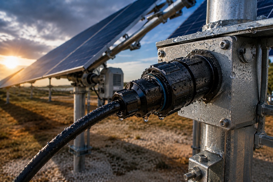
The front mating interface is only one possible entry point. Moisture can approach through the cable entry gland, backshell threads, cable jacket imperfections, panel cutouts, mounting hardware, or a damaged sealing gasket. It can also collect at a structural low point, migrate along the cable harness, or condense inside an enclosure when ambient temperatures drop rapidly.
An installation review should follow the moisture path from the upstream cable clamp down to the equipment interior:
● Cable Slope & Drip Loops: Verify whether the cable slopes toward the connector body. Ensure a dedicated drip loop redirects surface runoff below the entry point.
● Strain Relief: Confirm that the first fixed mounting point prevents cable weight or wind whip from transmitting mechanical tension to the backshell seal.
● Gland Compression: Ensure the cable enters the sealing gland within its specified OD (outer diameter) tolerance. The jacket should be round and undamaged, with no tape, labels, or irregular sleeving passing through the sealing zone.
● Mounting Orientation: Avoid positioning connectors directly under structural drip edges or inside unvented pockets that pool water. While protective caps reduce direct splash, they must not form trapped moisture traps that accumulate condensation.
2. Distinguish Ingress Leakage from Internal Condensation
Field troubleshooting requires distinguishing between external fluid entry and internal atmospheric condensation:
● External Leakage: Characterized by localized water trails, mineral deposits near gland threads, or liquid concentrated on one side of a connector housing.
● Internal Condensation: Typically appears as a uniform moisture film inside the shell after a rapid temperature drop (e.g., cool desert nights after hot daytime operation), caused by humid air trapped during initial assembly.
Before cleaning or replacing components during a field audit, document environmental conditions, recent rain events, mounting orientation, and deposit patterns. Photos taken prior to disassembly provide essential evidence. If an interface must be opened in the field, protect exposed contacts from airborne dust and inspect internal O-rings, thread condition, and mating faces before re-securing the connection.
3. Account for Salt Spray, Dust, and Galvanic Corrosion
In coastal or desert solar installations, environmental factors alter mechanical and electrical properties over time:
● Salt-Laden Moisture: Accelerates galvanic corrosion at dissimilar metal contact points, threaded couplings, damaged surface coatings, and exposed pin contacts.
● Abrasive Dust: Absorbs moisture and creates friction during mating or thermal expansion cycles, potentially compromising elastomer seals.
Visual inspections should compare installed units against a clean baseline. Look for surface discoloration, metal pitting, hard mineral deposits, gritty coupling action, swollen or hardened rubber seals, and contact oxidation.
Electrical diagnostic checks should go beyond simple continuity. Periodic low-level contact resistance testing or insulation resistance measurements under controlled conditions help identify degrading interfaces long before complete signal or power loss occurs.
4. Mitigate Dynamic Tracker Motion and Strain
Solar trackers are moving mechanical structures. Daily single-axis or dual-axis tracking, wind-induced vibration, and thermal expansion exert cyclic forces on interconnect harnesses. If cable management is inadequate, the connector backshell and coupling nut will absorb structural loads they were never designed to handle.
To maintain interface integrity across the full tracking envelope:
● Service Loops: Provide sufficient harness length to accommodate maximum tilt angles without creating excessive slack that could snag on structural members.
● Bend Radius Compliance: Ensure fixed routing clips maintain the cable manufacturer’s minimum dynamic bend radius throughout the movement arc. Never use the connector body as a primary cable clamp.
● Vibration Resistance: In high-vibration or high-cycle tracking environments, selecting a heavy-duty waterproof aviation plug with positive threaded locking or push-pull quick-latching mechanisms prevents gradual coupling backing-off.
● Torque Control: For threaded interfaces, follow specified assembly torque values during installation and maintenance. Applying a visual alignment stripe across mated coupling components allows technicians to perform rapid visual checks for rotational loosening.
5. Pre-Storm and Post-Event Inspection Protocol
A robust field management plan converts environmental exposure into repeatable maintenance routines:
Pre-Wet Season Baseline Check
1. Audit connector mounting orientations, drip loops, and cable clamp security.
2. Inspect sealing gaskets, coupling tightness, and alignment marks.
3. Identify high-risk zones (e.g., tracker rows nearest coastal boundaries or low structural drainage points).
Post-Storm Verification
1. Re-examine high-risk interfaces for visible moisture, seal displacement, or loosened coupling nuts.
2. Log electrical anomalies (such as ground fault alerts or intermittent telemetry dropouts) alongside physical observations.
3. Document physical conditions with photographs before performing corrective maintenance or cleaning.
Summary Checklist for Outdoor Interconnect Reliability
● Verify that rain, spray, runoff, and pooling water paths bypass the connector seal area.
● Ensure cable routing incorporates drip loops and strain-relief clamps.
● Confirm cable jacket OD matches gland compression tolerances.
● Check panel cutout dimensions, sealing gasket seating, and mounting hardware torque.
● Validate harness flexibility and clearance across the complete tracker motion envelope.
● Use positive-locking connector mechanisms designed for outdoor vibration.
● Establish baseline visual and electrical records before seasonal weather changes.
About the Author: Article contributed by industrial interconnect engineering specialists focused on harsh-environment power, signal, and data connectivity solutions for solar, robotics, and industrial automation applications.
Filed in: / Renewable Energy / Solar Trackers
Advertising